SkyWrap / OPGW / Optical Ground Wire
FiberRunner / Internal DuctRunner
Paran Fiber Optick Lighting
Fiber Optics Chandelier
Subsea Installation
Wednesday, July 29, 2009
Saturday, May 9, 2009
Fiber Optics Test Equipment - How To Clean Fiber End Ferrule
During testing & commissioning of fiber optics cable you might encounter unexplained or unexpected higher fiber loss. You have done your best in getting the lowest possible fiber jointing loss, you took proper and extra care during fiber installation by avoiding micro & macro bending and pulling cable with minimum force and yet you still encounter unexplained fiber optic cable loss.
The first thing you should do is to make sure that your fiber optics test equipment is properly set up. The second thing that you should take note is to have a clean fiber optics ferrule end surface. During installation your fiber optics connectors might exposed to dusty environment or you forget to use cap to cover your connector ferrule.
You could use either cotton with 99.99% Isoprophy alcohol to clean the end surface of fiber optics ferrule or following easy to use fiber cleaning method.
dB versus Optical Power Loss
dB vs. Optical Power Loss
In designing an optical link, the optical link loss budget must be calculated. This reflects the difference of power generated by the transmitter compared to the amount of light the receiver is set to receive. In calculating link loss budgets, first consider the output power of the transmitter. For example, most multimode transceivers have a minimum transmission value of -10dB; maximum receiver sensitivity is set at -17dB. The result is that in a multimode application, with a standard transceiver at 850nm, the dB budget is -7dB. This means that up to 7dB of power can be lost in the cable plant loss and the receiver will still detect an optical signal.
The following table shows the percentage of power lost and its corresponding dB value. At -7dB, only 20% of power is received and yet the optical signal is received successfully. A theoretically perfect optical device would have no internal losses and would transmit 100% of the power, thus having 0dB.
Using the dB budget determined by the transceiver, determine the attenuation value to be used. In the example given above, there is a dB budget of -7db. Assuming a tolerance of +/-1db, an attention value of between -6dB and -8dB is optimal. But there is the need to eliminate false failures, so an attenuation value of -6dB comes close to maximum stress for the device under test without the fear of incurring a failure rate of 50%.
Fiber Optics Test Equipment - Power Meter & Light Source
Power Meter & Light Source are used as final fiber optics cable test requirement. The test would indicate either fiber optics loss (after installation and jointings) is within specified fiber budget loss. If final fiber optics loss measurement is less than optimal fiber budget loss then the fiber optics would be accepted and finally handed over to client.
How to conduct Fiber Optics Loss ?
Power in a fiber optic system is like voltage in an electrical circuit - it's what makes things happen! It's important to have enough power, but not too much. Too little power and the receiver may not be able to distinguish the signal from noise; too much power overloads the receiver and causes errors too.
 Measuring power requires only a power meter (most come with a screw-on adapter that matches the connector being tested) and a little help from the network electronics to turn on the transmitter. Remember when you measure power, the meter must be set to the proper range (usually dBm, sometimes microwatts, but never "dB" that's a relative power range used only for testing loss!) and the proper wavelengths matching the source being used. Refer to the instructions that come with the test equipment for setup and measurement instructions (and don't wait until you get to the job site to try the equipment)!
To measure power, attach the meter to the cable that has the output you want to measure. That can be at the receiver to measure receiver power, or to a reference test cable (tested and known to be good) that is attached to the transmitter, acting as the "source", to measure transmitter power. Turn on the transmitter/source and note the power the meter measures. Compare it to the specified power for the system and make sure it's enough power but not too much.
In addition to our power meter, we will need a test source. The test source should match the type of source (LED or laser) and wavelength (850, 1300, 1550 nm). Again, read the instructions that come with the unit carefully.
We also need one or two reference cables, depending on the test we wish to perform. The accuracy of the measurement we make will depend on the quality of your reference cables. Always test your reference cables by the single ended method shown below to make sure they're good before you start testing other cables!
Next we need to set our reference power for loss our "0 dB" value. Correct setting of the launch power is critical to making good loss measurements!
 Turn on the source and select the wavelength you want for the loss test. Turn on the meter, select the "dBm" or "dB" range and select the wavelength you want for the loss test. Measure the power at the meter. This is your reference power level for all loss measurements. If your meter has a "zero" function, set this as your "0" reference.
Some reference books and manuals show setting the reference power for loss using both a launch and receive cable mated with a mating adapter. This method is acceptable for some tests, but will reduce the loss you measure by the amount of loss between your reference cables when you set your "0dB loss" reference. Also, if either the launch or receive cable is bad, setting the reference with both cables hides the fact. Then you could begin testing with bad launch cables making all your loss measurements wrong. EIA/TIA 568 calls for a single cable reference, while OFSTP-14 allows either method.
 There are two methods that are used to measure loss, which we call "single-ended loss" and "double-ended loss". Single-ended loss uses only the launch cable, while double-ended loss uses a receive cable attached to the meter also.
Single-ended loss is measured by mating the cable you want to test to the reference launch cable and measuring the power out the far end with the meter. When you do this you measure 1. the loss of the connector mated to the launch cable and 2. the loss of any fiber, splices or other connectors in the cable you are testing. This method is described in FOTP-171 and is shown in the drawing. Reverse the cable to test the connector on the other end.
In a double-ended loss test, you attach the cable to test between two reference cables, one attached to the source and one to the meter. This way, you measure two connectors' loses, one on each end, plus the loss of all the cable or cables in between. This is the method specified in OFSTP-14, the test for loss in an installed cable plant.
 While it is difficult to generalize, here are some guidelines:
- For each connector, figure 0.5 dB loss (0.7 max)
- For each splice, figure 0.2 dB
- For multimode fiber, the loss is about 3 dB per km for 850 nm sources, 1 dB per km for 1300 nm. This roughly translates into a loss of 0.1 dB per 100 feet for 850 nm, 0.1 dB per 300 feet for 1300 nm.
- For singlemode fiber, the loss is about 0.5 dB per km for 1300 nm sources, 0.4 dB per km for 1550 nm.
This roughly translates into a loss of 0.1 dB per 600 feet for 1300 nm, 0.1 dB per 750 feet for 1300 nm. So for the loss of a cable plant, calculate the approximate loss as:
Fiber Budget Loss = (0.5 dB X # connectors) + (0.2 dB x # splices) + fiber loss on the total length of cable
How to conduct Fiber Optics Loss ?
Power in a fiber optic system is like voltage in an electrical circuit - it's what makes things happen! It's important to have enough power, but not too much. Too little power and the receiver may not be able to distinguish the signal from noise; too much power overloads the receiver and causes errors too.
Measuring power requires only a power meter (most come with a screw-on adapter that matches the connector being tested) and a little help from the network electronics to turn on the transmitter. Remember when you measure power, the meter must be set to the proper range (usually dBm, sometimes microwatts, but never "dB" that's a relative power range used only for testing loss!) and the proper wavelengths matching the source being used. Refer to the instructions that come with the test equipment for setup and measurement instructions (and don't wait until you get to the job site to try the equipment)!To measure power, attach the meter to the cable that has the output you want to measure. That can be at the receiver to measure receiver power, or to a reference test cable (tested and known to be good) that is attached to the transmitter, acting as the "source", to measure transmitter power. Turn on the transmitter/source and note the power the meter measures. Compare it to the specified power for the system and make sure it's enough power but not too much.
Testing loss
Loss testing is the difference between the power coupled into the cable at the transmitter end and what comes out at the receiver end. Testing for loss requires measuring the optical power lost in a cable (including connectors ,splices, etc.) with a fiber optic source and power meter by mating the cable being tested to known good reference cable.In addition to our power meter, we will need a test source. The test source should match the type of source (LED or laser) and wavelength (850, 1300, 1550 nm). Again, read the instructions that come with the unit carefully.
We also need one or two reference cables, depending on the test we wish to perform. The accuracy of the measurement we make will depend on the quality of your reference cables. Always test your reference cables by the single ended method shown below to make sure they're good before you start testing other cables!
Next we need to set our reference power for loss our "0 dB" value. Correct setting of the launch power is critical to making good loss measurements!
Clean your connectors and set up your equipment like this:
Turn on the source and select the wavelength you want for the loss test. Turn on the meter, select the "dBm" or "dB" range and select the wavelength you want for the loss test. Measure the power at the meter. This is your reference power level for all loss measurements. If your meter has a "zero" function, set this as your "0" reference.Some reference books and manuals show setting the reference power for loss using both a launch and receive cable mated with a mating adapter. This method is acceptable for some tests, but will reduce the loss you measure by the amount of loss between your reference cables when you set your "0dB loss" reference. Also, if either the launch or receive cable is bad, setting the reference with both cables hides the fact. Then you could begin testing with bad launch cables making all your loss measurements wrong. EIA/TIA 568 calls for a single cable reference, while OFSTP-14 allows either method.
Testing Loss
There are two methods that are used to measure loss, which we call "single-ended loss" and "double-ended loss". Single-ended loss uses only the launch cable, while double-ended loss uses a receive cable attached to the meter also.Single-ended loss is measured by mating the cable you want to test to the reference launch cable and measuring the power out the far end with the meter. When you do this you measure 1. the loss of the connector mated to the launch cable and 2. the loss of any fiber, splices or other connectors in the cable you are testing. This method is described in FOTP-171 and is shown in the drawing. Reverse the cable to test the connector on the other end.
In a double-ended loss test, you attach the cable to test between two reference cables, one attached to the source and one to the meter. This way, you measure two connectors' loses, one on each end, plus the loss of all the cable or cables in between. This is the method specified in OFSTP-14, the test for loss in an installed cable plant.
What Loss Should You Get When Testing Cables?
While it is difficult to generalize, here are some guidelines:- For each connector, figure 0.5 dB loss (0.7 max)
- For each splice, figure 0.2 dB
- For multimode fiber, the loss is about 3 dB per km for 850 nm sources, 1 dB per km for 1300 nm. This roughly translates into a loss of 0.1 dB per 100 feet for 850 nm, 0.1 dB per 300 feet for 1300 nm.
- For singlemode fiber, the loss is about 0.5 dB per km for 1300 nm sources, 0.4 dB per km for 1550 nm.
This roughly translates into a loss of 0.1 dB per 600 feet for 1300 nm, 0.1 dB per 750 feet for 1300 nm. So for the loss of a cable plant, calculate the approximate loss as:
Fiber Budget Loss = (0.5 dB X # connectors) + (0.2 dB x # splices) + fiber loss on the total length of cable
Monday, April 20, 2009
Fiber Optics Test Equipment - Splicing Machine
What is Fiber Optics Splicing ?
Fiber Optics Splicing in other words is equivalent to joint two sections of fiber optics.
In any installation of fiber optics cable, the recommended length of each section fiber optics cable is max 2 km. So if you have to install 6 km of fiber optics cable from Station A to Station B then you need to splice/joint 2 section of fiber optics cable.
There two methods on jointing / splicing fiber optics. They are mechanical splicing and fusion splicing and you might have to choose which technique best fits your economic and performance objective.


 What is Fusion Splicing ?
Fusion Splicing is a method to joint permanently two fibers by welding them together by an electronic arc machine called Splicing Machine.
What is Mechanical Splicing ?
Mechanical splicing is an optical junction where the fibers are precisely aligned and held in place by a self-contained assembly, not a permanent bond. This method aligns the two fiber ends to a common centerline, aligning their cores so the light can pass from one fiber to another.
Step 1: Preparing the fiber - Strip the protective coatings, jackets, tubes, strength members, etc. leaving only the bare fiber showing. The main concern here is cleanliness.
Step 2: Cleave the fiber - The process is identical to the cleaving for fusion splicing but the cleave precision is not as critical.
Fibrlok Mechanical Splicing KitStep 3: Mechanically join the fibers - There is no heat used in this method. Simply position the fiber ends together inside the mechanical splice unit. The index matching gel inside the mechanical splice apparatus will help couple the light from one fiber end to the other. Older apparatus will have an epoxy rather than the index matching gel holding the cores together.
Step 4: Protect the fiber - the completed mechanical splice provides its own protection for the splice.
There are many types of Mechanical Splices available in the market. Most commons type are UltraSplice, 3M Fibrlok, SpliceConnect etc,
Fiber Optics Splicing in other words is equivalent to joint two sections of fiber optics.
In any installation of fiber optics cable, the recommended length of each section fiber optics cable is max 2 km. So if you have to install 6 km of fiber optics cable from Station A to Station B then you need to splice/joint 2 section of fiber optics cable.
There two methods on jointing / splicing fiber optics. They are mechanical splicing and fusion splicing and you might have to choose which technique best fits your economic and performance objective.
What is Fusion Splicing ?Fusion Splicing is a method to joint permanently two fibers by welding them together by an electronic arc machine called Splicing Machine.
What is Mechanical Splicing ?
Mechanical splicing is an optical junction where the fibers are precisely aligned and held in place by a self-contained assembly, not a permanent bond. This method aligns the two fiber ends to a common centerline, aligning their cores so the light can pass from one fiber to another.
Step 1: Preparing the fiber - Strip the protective coatings, jackets, tubes, strength members, etc. leaving only the bare fiber showing. The main concern here is cleanliness.
Step 2: Cleave the fiber - The process is identical to the cleaving for fusion splicing but the cleave precision is not as critical.
Fibrlok Mechanical Splicing KitStep 3: Mechanically join the fibers - There is no heat used in this method. Simply position the fiber ends together inside the mechanical splice unit. The index matching gel inside the mechanical splice apparatus will help couple the light from one fiber end to the other. Older apparatus will have an epoxy rather than the index matching gel holding the cores together.
Step 4: Protect the fiber - the completed mechanical splice provides its own protection for the splice.
There are many types of Mechanical Splices available in the market. Most commons type are UltraSplice, 3M Fibrlok, SpliceConnect etc,
Sunday, April 19, 2009
Fiber Optics Test Equipment - OTDR
What is an OTDR ?
Short for Optical Time Domain Reflectometer, an instrument that analyzes the light loss in an optical fiber cable in optical network trouble shooting. An OTDR injects a short, intense laser pulse into the optical fiber and measures the backscatter and reflection of light as a function of time. The reflected light characteristics are analyzed to determine the location of any fiber optic breaks or splice losses.
The OTDR tester operates by sending an optical pulse of energy, timing and response, a d analyzing the shape of the pulse to determine the type of change in the transmission line that caused the signal reflection.
How does OTDR machine look like ?
This is called mini-OTDR which main functions are to determine fiber length, fiber continuity and approximate fiber damaged location.
There are few brands of mini-OTDR in the market namely by Anritsu, Yokogawa (used to be known as ANDO), NOYES and other few brands either from Europe, USA, Japan or China.
There is another type of lightweight OTDR which is called hand-held OTDR. The handheld OTDR is mainly to be used to test short distance fiber cable length in particular the Fibe r-To-The-Home fiber installation. The most common and popular handheld OTDR being used in Malaysia is of NOYES brand.
How Does an OTDR Work ?

Figure 1. Scattering in an optical fiber
Figure 2. OTDR Display
Short for Optical Time Domain Reflectometer, an instrument that analyzes the light loss in an optical fiber cable in optical network trouble shooting. An OTDR injects a short, intense laser pulse into the optical fiber and measures the backscatter and reflection of light as a function of time. The reflected light characteristics are analyzed to determine the location of any fiber optic breaks or splice losses.
The OTDR tester operates by sending an optical pulse of energy, timing and response, a d analyzing the shape of the pulse to determine the type of change in the transmission line that caused the signal reflection.
How does OTDR machine look like ?
This is called mini-OTDR which main functions are to determine fiber length, fiber continuity and approximate fiber damaged location.
There are few brands of mini-OTDR in the market namely by Anritsu, Yokogawa (used to be known as ANDO), NOYES and other few brands either from Europe, USA, Japan or China.
There is another type of lightweight OTDR which is called hand-held OTDR. The handheld OTDR is mainly to be used to test short distance fiber cable length in particular the Fibe
 r-To-The-Home fiber installation. The most common and popular handheld OTDR being used in Malaysia is of NOYES brand.
How Does an OTDR Work ?
In the fiber, light is scattered in all directions, including back toward the source as shown in Figure 1. The OTDR uses this "backscattered light" to make its measurements. It sends out a very high power pulse and measures the light coming back. At any point in time, the light the OTDR sees is the light scattered from the pulse passing through a region of the fiber. Think of the OTDR pulse as being a "virtual source" that is testing all the fiber between itself and the OTDR as it moves down the fiber. Since it is possible to calibrate the speed of the pulse as it passes down the fiber, the OTDR can correlate what it sees in backscattered light with an actual location in the fiber. Thus it can create a display of the amount of backscattered light at any point in the fiber, Figure 2.

There are some calculations involved. Remember the light has to go out and come back, so you have to factor that into the time calculations, cutting the time in half and the loss calculations, since the light sees loss both ways. The power loss is a logarithmic function, so the power is measured in dB.
Friday, March 27, 2009
Types of Fiber Optics
There two main type of fiber optics :-
a. Singlemode
b. Multimode
a. Singlemode
b. Multimode
Single mode fiber has a very small core causing light to travel in a straight line and typically has a core size of 8 or 10 microns. It has unlimited bandwidth that can go unrepeated for over 80 km, depending on the type of transmitting equipment. Single mode fiber has enormous information capacity, more than multimode fiber.
Multimode fiber supports multiple paths of light and has a much larger core and has a core size of 50 or 62.5 microns. The light travels down a much larger path in multimode fiber, allowing the light to go down several paths or modes.
Multimode fiber can be manufactured in two ways: step-index or graded index. Step-index fiber has an abrupt change or step between the index of refraction of the core and the index of refraction of the cladding. Multimode step-index fibers have lower bandwidth than other fiber designs.
Graded index fiber was designed to reduce modal dispersion inherent in step index fiber. Modal dispersion occurs as light pulses travel through the core along higher and lower order modes. Graded index fiber is made up of multiple layers with the highest index of refraction at the core. Each succeeding layer has a gradually decreasing index of refraction as the layers move away from the center. High order modes enter the outer layers of the cladding and are reflected back towards the core. Multimode graded index fibers have less attenuation (loss) of the output pulse and have higher bandwidth than multimode step-index fibers.
Table 1: Single Mode and Multimode Characteristics
| Single Mode Fiber | Multimode Fiber | |
| Bandwidth | High | Lower |
| Signal Quality | High | Lower |
| Main Source of Attenuation | Chromatic Dispersion | Modal Dispersion |
| Fiber Designs | Step index, & Dispersion shifted | Step index & Graded index |
| Application | Long transmission, higher bandwidth | Short transmission, lower bandwidth |
Single mode step-index fibers are not affected by modal dispersion because light travels a single path. Single mode step-index fibers experience light pulse stretching and shrinking via chromatic dispersion. Chromatic dispersion happens when a pulse of light contains more than one wavelength. Wavelengths travel at different speeds, causing the pulse to spread. Dispersion can also occur when the optical signal gets out of the core and into the cladding, causing shrinking of the total pulse.
Single mode shifted fiber uses multiple layers of core and cladding to reduce dispersion. Dispersion shifted fibers have low attenuation (loss), longer transmission distances, and higher bandwidth.
In discussing fiber cables you will hear the terms IFC and OSP. IFC refers to an Intrafacility fiber cable. These types of cables are designed for use with in a controlled environment such as a building or inside equipment. Since the cable is used within a building the cable requires less physical protection and more flexibility. Outside plant cable, or OSP, are used in hostile environments, exposed to extreme temperatures, rain, and wind. The cables are more robust and have extra layers of buffering and sheathing to protect the fiber.
Fibers are assembled into either stranded or ribbon cables. Stranded cables are individual fibers that are bundled together. Ribbon cable is constructed by grouping up to 12 fibers and coating them with plastic to form a multi fiber ribbon. Stranded and ribbon fiber bundles can be packaged together into either loose or tight buffering cable.
Table 2: Cable Characteristics
| Loose Buffered Cable | Tight Buffered Cable |
| Each individual fiber bundle moves freely within the inner sheath | Fiber elements are held in place within the cable |
| Protects from tensile factors | Smaller in diameter with fewer fibers |
| Less expensive | More flexible for manipulation |
| More robust | More sensitive to outside forces |
| Higher fiber counts | Less toxic when burned |
| Optimized for long runs | Used in intrafacility applications |
| Used in OSP applications (aerial, buried, or submerged) | Cables are either distribution or breakout designs. All fiber bundles are in a single jacket or each has a separate jacket |
Fibre Connector Termination
Video 1 on Fiber Connector Termination
Video 2 on Fiber Connector Termination
Video 3 on Fiber Connector Termination
Video 4 on Fiber Connector Quick Termination Method
There are quite a few Quick Fiber Termination Connectors available in the market from various designed from various fiber optics designers.
Source :
Video 2 on Fiber Connector Termination
Video 3 on Fiber Connector Termination
Video 4 on Fiber Connector Quick Termination Method
There are quite a few Quick Fiber Termination Connectors available in the market from various designed from various fiber optics designers.
| JACKETED CABLE PREPARATION (for cable > 2.6mm) | ||
| 1. | Insert the end of the cable into the small end of the rubber boot and then into the small end of the metal crimp ferrule (figure 1). Figure 1: Insert Cable into the boot and crimp ferrule | |
| 2. | Using the Ideal Stripmaster tool , remove approximately 1.5" of the outer jacket. | |
 Jacket Stripping | ||
| 3. | Twist the Kevlar strength members with the thumb and forefinger tightly and cut with a pair of snips - use Figure 2 as a guide. | |
| 4. | Mark the appropriate buffer strip length (figure 2) using a felt tip pen. Do not use a hard tip pen as this may damage the fiber. Figure 2: Recommended strip length | |
| 5. | Strip the buffer using the Tec-Cut tool for 900 µm tight buffer or the adjustable Miller stripper for other cable construction types (loose tube, 200 µm or 500 µm buffer). | |
| 5(a). | Hold the Tec-Cut tool with the self-guide mechanism toward the center of the cable (Figure 3). For best results, remove the entire buffer in two or three segments. Spread the handles apart and place the buffer in the self-guide mechanism. Close the handles together until the blade "bites" into the buffer. Hold the tool firmly - perpendicular to the fiber - and pull the tool and buffer material away from you in a smooth fashion until the buffer material is removed from the fiber. Remove any buffer residue remaining in the tool. The blade should occasionally be cleaned with a dry brush. Note: Use the Tec-Cut tool for buffer removal only.  Figure 3: Strip the buffer material as shown | |
| 5(b). | Place the fiber in the V-groove and close the handle. Tilt the tool 45 degrees and, squeezing the handles lightly, strip the buffer with a straight forward motion.  Figure 4: The Miller stripper is used for all buffer sizes. | |
| | Clean the fiber with alcohol or as recommended by the manufacturer. Cleanliness of the fiber is essential to the success of the termination. | |
| 6. | Insert the clean fiber into the connector to ensure the buffer strip length is correct and the ferrule hole is the proper size. If properly stripped, the rear body of the connector should not be resting on the outer jacket, but should be as close as possible - refer to Figure 5. If the fiber meets resistance, rotate the ferrule while applying light forward pressure. If still unsuccessful, back the fiber out and check to see if the fiber hole is obstructed by holding the ferrule up to a light. If obstructed, use cleaning wire to remove the obstruction. Simply draw the cleaning wire through the ferrule hole by feeding the wire through the ferrule or rear body of the connector. It may be necessary to repeat this process to ensure that all of the obstruction has been removed. Re-cleaning the fiber may also be necessary. For single mode applications, a larger hole size may be required if the clean fiber will not fit into a clean, unobstructed ferrule.  Figure 5: Drawing of buffer properly seated against the ferrule | |
| EPOXY PREPARATION | ||
| 7. | For dependable results, Amphenol recommends Epo-Tek 353ND or TRA-BOND F253 epoxy when heat curing. All Amphenol cable assemblies used for qualification testing were terminated using one of these heat cure epoxies. TRA-BOND F113SC epoxy is recommended for an overnight cure at room temperature. These epoxies demonstrate the proper viscosity and bonding characteristics for successful terminations. Substitute epoxies may hinder fiber insertion and cause the fiber to crack during the curing cycle or during environmental changes. First, determine which epoxy will be used and prepare it as follows:
353ND: This epoxy should be a light amber color when thoroughly mixed. The workable pot life is 4 hours and a 4 minute cure time at 150øC is required. The epoxy will experience a color change from amber to red upon cure. This epoxy should not be refrigerated. F253: The F253 epoxy should be a pea green color when thoroughly mixed. The workable pot life is approximately two hours. It will change color from green to blue during this time. If refrigerated, the pot life can be extended. Once the viscosity has substantially increased, the epoxy should be discarded. The F253 epoxy takes four minutes at 150°C to cure. F113SC: This epoxy should be dark blue when thoroughly mixed. The workable pot life is approximately 45 minutes and a 12-hour cure time at 24°C is required. This epoxy cannot be refrigerated and reused. | |
| 8. | Remove the plunger from the syringe. Remove the plastic cap from the syringe and replace it with the green dispensing tip. Do not substitute syringe tips. Cut the corner of the epoxy packet and squeeze all of the epoxy into the rear of the syringe. Insert the plunger just inside the rear of the syringe without pushing on it to prevent epoxy from spilling. While tilting the syringe upward, slowly push the plunger forward to evacuate any air from the syringe. | |
| 9. | Holding the syringe vertically on the bench top, place the connector onto the dispensing tip to a positive stop as shown in Figure 6. Apply downward pressure on the connector and syringe until a tiny spot of epoxy appears on the face of the ferrule. Relieve pressure immediately by pulling back on the plunger and then back out the syringe. NOTE: Excessive amounts of epoxy within the connector may adversely affect the performance of the Termination  Figure 6: Place the connector on syringe tip to inject | |
| FIBER INSERTION | ||
| 10. | Hold the connector and cable as shown in Figure 7 and insert the fiber carefully into the connector until .25" of fiber protrudes. Slight rotation of the connector may assist the insertion. (TIP: It may be helpful to place both elbows on the work surface for support and stability.)  Figure 7: Rotate the connector slightly to ease fiber insertion. | |
| 11. | Holding the connector and cable in one hand as shown in Figure 8, back the fiber slowly out of the connector until the tip of the fiber is just inside the ferrule. With the other hand, thoroughly clean ALL epoxy from the face of the ferrule with a dry wipe. Once cleaned, fully insert the fiber with a slow and continuous motion. Epoxy should be absent from the ferrule surface upon completion of this step. With the edge of a wipe, also gently remove any epoxy remaining on the fiber near the ferrule surface. NOTE: For a successful termination, all epoxy must be removed from the ferrule surface.  Figure 8: Wipe any epoxy from the face of the ferrule. | |
| CRIMPING | ||
| 12. | Pull any Kevlar strength members from under the connector body and distribute them evenly around the connector body. With the dispensing tip, apply one small drop of epoxy to the knurled portion of the rear body. Slide the crimp ferrule up onto the rear portion of the connector over the strength members until it seats just under the coupling nut. Hold the connector with the forefinger applying light downward pressure to ensure that the connector is fully seated onto the buffer (see Figure 9). If the straight crimp ferrule is used, position the .178" cavity of the crimp tool up against the rear portion of the connector. Crimp the entire length of the ferrule. If the stepped crimp ferrule is used, crimp the large diameter with the .178" cavity and the smaller diameter with the .151" cavity, as shown in Figure 10. The .151" die used with the stepped crimp ferrule will accommodate a jacket with a minimum outer diameter of 2.6 mm. For 953 terminations, slide the boot over the crimp ferrule. Optional: The boot may be slid up on the 905 or 906 Smarts, 944, or the 954 connectors for ease of handling after heat curing. Then, pull back the boot so the connector can be correctly inserted into the polishing tool. | |
 Figure 9: Use the .178" cavity die to crimp the entire length of the straight crimp ferrule. | ||
 Figure 10: Use the .178" and .151" cavity dies to crimp the stepped crimp ferrule. | ||
| HEAT CURING | ||
| 13. | Use the Amphenol oven (p/n 927-100-2084 for the multi-port oven shown in Figure 11) to provide the proper cure temperature, 140 - 150°C, for the TRA-BOND F253 and Epo-Tek 353ND epoxies. Turn on the oven. The indicator light will illuminate in approximately 3 minutes when the oven has reached the appropriate temperature. Carefully place the connector into the curing oven. The connector is to be heated for 4 minutes. CAUTION: The connector will be hot. The boot, however, does not get hot and can be handled immediately.  Figure 11: Top view of multi-port curing oven. | |
| CLEAVING | ||
| 14. | Hold the cleave tool as shown in Figure 12. Guide the fiber along the slot on the side of the tool and insert the ferrule into the cleave tool to a positive stop. Caution should be exercised not to break the fiber. Holding the connector away from you, completely depress the trigger to cleave the fiber. The cleave tool is factory adjusted to a height of approximately 125 micron above the ferrule surface. See page 10 for troubleshooting tips should poor cleave result. Remove the connector from the tool and, with a piece of tape, dispose of the fiber waste. NOTE: Epoxy on the ferrule face or fiber may damage the diamond blade in the cleave tool. If necessary, contact the factory for blade refurbishment. CAUTION: SAFETY GLASSES SHOULD BE WORN DURING CLEAVING.  Figure 12: Ensure the ferrule is fully seated against | |
| GRINDING | ||
| 15. | Hold the connector in one hand and a sheet of yellow 12 micron lapping film in the other. Very gently and with very little pressure, complete 10-15 circular strokes, 1 mm in diameter, to remove any sharp burrs or "hackle" from the cleaved fiber. (See Figure 13).  Figure 13: Use only the weight of the film as pressure. | |
| 16. | Slide a sheet of 12-micron lapping film (gritty side up) into the grinding track. The lapping film should fit beneath the lips on the interior borders of the track. Install the connector into the Amphenol constant force polishing fixture (see Figures 14a and 14b). If the connector is assembled into the polishing tool correctly, slight pressure on the ferrule (be careful not to touch the fiber) with the thumbnail should result in a spring action. If this is not the case the connector should be removed and reinserted. | |
 Figure 14a: Insert the 906 or 906 SMArt, 944 FC or 954 SC connector into the appropriate polishing disk and assemble the handle until it seats completely. | ||
 Figure 14b: Insert the 953 ST connector by aligning the key to the slot on the tool. Push and lock the connector into position by rotating the nut until it seats. | ||
 Figure 15: Hold the polishing fixture, not the connector nut. Do not allow the polishing tool to leave the track during grindings. | ||
| 17. | Place the polishing tool on the track and perform 7 strokes along the entire length of the track (See Figure 15). NOTE: Back and forth is considered two strokes. Using an alcohol wipe, dab the connector face to remove any abrasive particles before continuing to the next step. Replace the lapping film every 6 connectors. | |
| FINAL POLISHING | ||
| 18. | Remove the backing of a piece of 0.3-micron white lapping film and place the film onto the polishing board. Using an alcohol wipe, ensure the surface is clean and the film is free of any air bubbles. Begin polishing slowly and with light pressure. Complete 15-25 circular strokes approximately 2" in diameter using the entire length of film. As the tracks on the film become wider, gradually add more pressure. If the film tears the fiber is too and should receive two additional strokes on the grinding track. Remove the connector from the polishing tool and clean it with an alcohol wipe. Clean the film after every connector is Polished and replace it every 4-5 connectors.  Figure 16: Wipe the film with an alcohol wipe between polishes. | |
| FINAL ASSEMBLY (SC SIMPLEX OR DUPLEX CONNECTOR ONLY) | ||
| 19. | After a successful polish has been completed, assemble the blue coupling sleeve. This is achieved by first sliding up the bend relief boot. Insert the coupling sleeve, knurled end first, over the white body. Orient the sleeve so the tapered side of the sleeve fits into the tapered side of the body (see Figure 17). Hold onto the rear body of the connector tightly so the cable doesn't bend while assembling the sleeve. The coupling sleeve should lock into place when properly seated. Pulling on the sleeve in an outward motion should not free the coupling sleeve from the body. It should, however, be free to slide back and forth with little resistance  Figure 17: The coupling sleeve and plug frame must be oriented correctly to ensure proper assembly. | |
| INSPECTION | ||
| 20. | Place the appropriate adapter (see inset in Figure 18) on the microscope. Separate the arms of the microscope to turn on the light. Slowly adjust the focus knob on the side of the scope until the connector face comes into sharp focus. Note: FC/SC - Check for frozen springs by depressing the ferrule on a padded surface. If the ferrule resists movement, it is likely that too much epoxy was used and the connector is "frozen." Use only the Amphenol recommended syringe tip for epoxy injection. Figures 19a-d below show examples of acceptable and unacceptable polishes as viewed under the microscope. An acceptable polish will show the core free of any imperfections (Figure 19a). Figure 19b shows an unacceptable polish due to excess epoxy that was not properly removed from the top face of the ferrule - see Step 11. Another example of an unacceptable polish shows the core with pits, scratches, cracks, or darkness (Figure 19c). Figure 19d depicts the result of excessive grinding on the grinding track - see Step 18. If a poor polish results, refer to the troubleshooting tips.  Figure 18: The fiber end face should be inspected after polishing. | |
 Figure 19a: Acceptable polish | ||
 Figure 19b: Unacceptable Polish | ||
 Figure 19c: Unacceptable Polish | ||
 Figure 19d: Unacceptable Polish | ||
| BARE FIBER CABLE PREPARATION | ||
| 1. | Place the bare fiber bend relief boot on the bare fiber cable. The tapered portion of the boot should be placed toward the center of the cable. | |
| 2. | Use Figure 20 below to determine the proper strip length for the bare fiber. Figure 20: Bare fiber strip lengths for various connector types - SMArt, ST, FC, and SC. | |
| 3. | Follow the buffer stripping procedure as described in Step 5 of the Cable Preparation procedure for Jacketed Fiber. | |
| 4. | Proceed with the steps as previously described in both Epoxy Preparation and Fiber Insertion. | |
| 5. | Slide the bare fiber bend relief boot up over the rear body of the connector | |
| 6. | After placing the connector into the curing oven, ensure the buffer is bottomed on the inside of the connector (as indicated in Figure 21). This may be accomplished by applying a gentle downward force on the buffered fiber toward the connector. NOTE: The remaining buffered fiber should be supported to ensure the buffer remains seated in the connector throughout the heat cure process. | |
 Figure 21: The bare fiber is properly seated against the ferrule. | ||
| 7. | When the epoxy has fully cured, the connector may be removed from the curing oven. | |
| 8. | Proceed with Cleaving, Grinding, Polishing, Final Assembly and Inspection, as previously described. *SMArt connectors are not supplied with bare fiber boots as standard product. However, packaged solutions are available. | |
| TROUBLESHOOTING TIPS | ||
| CRACKS | ||
| ||
| SCRATCHES/PITS | ||
| ||
| NO LIGHT | ||
| ||
| HIGH INSERTION LOSS | ||
| ||
| CLEAVE TOOL CARE AND PRECAUTIONS | ||
The following steps for proper care and handling will increase the longevity of the cleave tool:
The cleave tool is factory adjusted and set to a proper cleave tool height. Most cleave tool malfunctions are caused by dirt or chips on the diamond blade and not due to improper adjustments. Clean the blade thoroughly and gently with an alcohol saturated swab. Inspect under a microscope to ensure that it is clean and undamaged. Handle the cleave tools with care for long lasting blade usage. If the blade is damaged, do not attempt to adjust the tool. The cleave tool is properly adjusted in the factory prior to shipping. Amphenol can rebuild the tool | ||
| 10 STEPS TO TERMINATE! This is a quick reference to the termination procedure detailed previously. | ||
| 1. | Place boot and crimp ferrule on cable and strip to appropriate lengths. Size the connector to determine if the 125 micron or 126 micron connector ferrule should be used. | |
| 2. | Mix epoxy thoroughly and load syringe. Place the connector on the dispensing tip to a positive stop and inject the epoxy until a bead appears on the ferrule surface. Remove the syringe. | |
| 3. | Insert the fiber into the connector until .25" protrudes. Retract the fiber just beneath the ferrule surface and clean the surface with a dry wipe. Reinsert the fiber until the buffer material is seated against the ferrule. The fiber and ferrule surface must be epoxy free at this point. | |
| 4. | Slide the crimp ferrule up and over the strength members. Use the .178" die if the straight crimp ferrule is used and the .178" and .151" dies if the stepped crimp ferrule is used. | |
| 5. | Allow to cure 4 minutes using the Amphenol curing oven. | |
| 6. | Cleave the fiber. | |
| 7. | Hold a piece of 12 micron film over the fiber and lightly complete 10-15 small circular strokes. | |
| 8. | Place the connector into the constant force polishing tool. Slide a sheet of 12 micron film in the grinding track, and complete 8 strokes (back and forth is two strokes). | |
| 9. | Clean the connector face. Place a sheet of .3 micron film on a smooth hard surface. Complete 820 circular strokes approximately 2" in diameter. Begin polishing slowly and with light pressure. If the film tears, the fiber should receive an additional 2 strokes on the 12 micron film in the grinding track. (If terminating a 954 SC connector, place the blue coupling sleeve onto the white body.) | |
| 10. | Clean and inspect the fiber. | |
Source :
Wednesday, March 25, 2009


Monday, March 23, 2009
Connector Loss - Insertion Loss & Return Loss
Connector and Splice Loss Mechanisms

End gaps cause two problems, insertion loss and return loss. The emerging cone of light from the connector will spill over the core of the receiving fiber and be lost. In addition, the air gap between the fibers causes a reflection when the light encounters the change n refractive index from the glass fiber to the air in the gap. This reflection (called fresnel reflection) amounts to about 5% in typical flat polished connectors, and means that no connector with an air gap can have less than 0.3 dB loss. This reflection is also referred to as back reflection or optical return loss, which can be a problem in laser based systems. Connectors use a number of polishing techniques to insure physical contact of the fiber ends to minimize back reflection. On mechanical splices, it is possible to reduce back reflection by using non-perpendicular cleaves, which cause back reflections to be absorbed in the cladding of the fiber.
The end finish of the fiber must be properly polished to minimize loss. A rough surface will scatter light and dirt can scatter and absorb light. Since the optical fiber is so small, typical airborne dirt can be a major source of loss. Whenever connectors are not terminated, they should be covered to protect the end of the ferrule from dirt. One should never touch the end of the ferrule, since the oils on one's skin causes the fiber to attract dirt. Before connection and testing, it is advisable to clean connectors with lint-free wipes moistened with isopropyl alcohol.
Two sources of loss are directional; numerical aperture (NA) and core diameter. Differences in these two will create connections that have different losses depending on the direction of light propagation. Light from a fiber with a larger NA will be more sensitive to angularity and end gap, so transmission from a fiber of larger NA to one of smaller NA will be higher loss than the reverse. Likewise, light from a larger fiber will have high loss coupled to a fiber of smaller diameter, while one can couple a small diameter fiber to a large diameter fiber with minimal loss, since it is much less sensitive to end gap or lateral offset.
These fiber mismatches occur for two reasons. The occasional need to interconnect two dissimilar fibers and production variances in fibers of the same nominal dimensions. With two multimode fibers in usage today and two others which have been used occasionally in the past and several types of singlemode fiber in use, it is possible to sometimes have to connect dissimilar fibers or use systems designed for one fiber on another. Some system manufacturers provide guidelines on using various fibers, some don't. If you connect a smaller fiber to a larger one, the coupling losses will be minimal, often only the fresnel loss (about 0.3 dB). But connecting larger fibers to smaller ones results in substantial losses, not only due to the smaller cores size, but also the smaller NA of most small core fibers.
- Connector Ferrule Shapes & Polishes
- Fiber optic connectors can have several different ferrule shapes or finishes, usually referred to as polishes. early connectors, because they did not have keyed ferrules and could rotate in mating adapters, always had an air gap between the connectors to prevent them rotating and grinding scratches into the ends of the fibers.
- Beginning with the ST and FC which had keyed ferrules, the connectors were designed to contact tightly, what we now call physical contact (PC) connectors. Reducing the air gap reduced the loss and back reflection (very important to laser-based singlemode systems ), since light has a loss of about 5% (~0.25 dB) at each air gap and light is reflected back up the fiber. While air gap connectors usually had losses of 0.5 dB or more and return loss of 20 dB, PC connectors had typical losses of 0.3 dB and a return loss of 30 to 40 dB.
- Soon thereafter, it was determined that making the connector ferrules convex would produce an even better connection. The convex ferrule guaranteed the fiber cores were in contact. Losses were under 0.3dB and return loss 40 dB or better. The final solution for singlemode systems extremely sensitive to reflections, like CATV or high bitrate telco links, was to angle the end of the ferrule 8 degrees to create what we call an APC or angled PC connector. Then any reflected light is at an angle that is absorbed in the cladding of the fiber.

Insertion loss refers to the fiber optic light loss caused when a fiber optic component insert into another one to form the fiber optic link. Insertion loss can result from absorption, misalignment or air gap between the fiber optic components. We want the insertion loss to be as less as possible. Our fiber optic components insertion loss is less than 0.2dB typical, less than 0.1dB types available on request.
Return loss is the fiber optic light gets reflected back at the connection point. The higher the return loss is means the lower reflection and the better the connection is. According to industry standard, Ultra PC polished fiber optic connectors return loss should be more than 50dB,Angled polished generally return loss is more than 60dB.PC type should be more than 40dB.
Source
Fiber Ferrule Connector Tip :- PC, UPC , APC or SPC ??
This short video will explain briefly on the difference of polishing fiber ferrule tip in terms of PC or APC or UPC . If you encounter a supplier quoted FC/PC to FC/PC or SC/APC to SC/APC then you know from now the difference between PC/APC/UPC..
Typical Fiber Optic Connector Polish Types | |
| Style | Description |
| Angled PC | The end face of the connector is angled to achieve better back reflection results mechanically. Back reflection is the same as the Enhanced Ultra PC. Used often in CATV applications. |
| PC | Physical Contact. The end face of the connector is convex. The core of the fiber is located at the high point of this surface. Offers good basic performance. In singlemode applications the back reflection results must fall between -30dB and -39dB. |
| Super PC | Modified PC Polish. Back reflection of -40dB to 49dB. |
| Ultra PC | Modified PC Polish. Back reflection of -50dB to 59dB. Enhanced Ultra PC-A modified PC policy that produces back reflection of -60dB or better and is the best performance available. |
Sunday, March 22, 2009
Safety & PreCaution on Handling Fiber Optics
When most people think of safety in fiber optic installations, the first thing that comes to mind is eye damage from laser light in the fiber. They have an image of a laser burning holes in metal or perhaps burning off warts. While these images may be real for their applications, they have little relevance to most types of fiber optic communications. Eye safety is an issue, but usually not from light in the fiber. However, fiber optics installation is not without risks.
- Eye Safety
Optical sources used in fiber optics, especially LEDs used in premises networks, are of much lower power levels than used for laser surgery or cutting materials. Even the output of OTDRs, WDM and fiber amplifier systems, which are much higher than LED systems, are still well below that used in laser surgery or machining. - The light that exits an optical fiber is also spreading out in a cone, so the farther away from the end of the fiber your eye is, the lower the amount of power your eye receives. If you are using a microscope, which can efficiently focus all the light into your eye, it should have infrared filters to reduce the danger of invisible infrared light.
- The infrared light in fiber optic links is at a wavelength that cannot penetrate your eye easily because it's absorbed by the water in your eyeball.
Light in the 1300-1550 nm range is unlikely to damage your retina, but might harm the cornea or lens.
- A typical laser pointer, which has a beam that is collimated (not expanding), and is at visible wavelength (650 nm) where the eye is transparent, is probably more danger to the retina than a fiber optic link.
That being said, it's not a good idea to look into a fiber unless you know no source is being transmitted down it. Since the light is infrared, you can't see it, which means you cannot tell if there is light present by looking at it. You should always check the fiber with a power meter before examining it.
The real issue of eye safety is getting fiber scraps into the eye. As part of the termination and splicing process, you will be continually exposed to small scraps of bare fiber, cleaved off the ends of the fibers being terminated or spliced. These scraps are very dangerous. If they get into your eyes, they are very hard to flush out and will probably lead to a trip to the emergency room at the hospital. Whenever you are working with fiber, wear safety glasses!
Bare Fiber SafetyThe broken ends of fibers and scraps of fiber created during termination and splicing can be extremely dangerous. The ends are extremely sharp and can easily penetrate your skin. They invariably break off and are very hard to find and remove. Sometimes a pair of tweezers and perhaps a magnifying glass will get them out. Most of the time, you have to wait to let them infect and work themselves out, which can be painful!
Be careful when handling fibers to not stick the broken ends into your fingers. Dispose of all scraps properly. Some people keep a piece of double stick tape on the bench to stick fiber scraps onto. I prefer to use a dedicated container for all fiber scraps. In our training programs, we use the same paper containers used for takeout at the deli, in the pint size, with a lid. We put all the scraps in the container, then when finished, put on the lid, tape it and dispose of it later. Do not drop fiber scraps on the floor where they will stick in carpets or shoes and be carried elsewhere-like home!
Obviously do not eat or drink anywhere near the work area. Fiber scraps can get into food or drink and be swallowed. The scraps can imbed themselves in you digestive system and never be found. Doesn't sound too appetizing, does it?!
Materials Safety
Fiber optic splicing and termination use various chemical cleaners and adhesives as part of the processes. Normal handling procedures for these substances should be observed. If you are not certain of how to deal with them, ask the manufacturer for a MSDS. Always work in well-ventilated areas. Avoid skin contact as much as possible, and stop using chemicals that cause allergic reactions. Even simple isopropyl alcohol, used as a cleaner, is flammable and should be handled carefully.
Fire Safety
Note that fusion splicers use an electric arc to make splices, so care must be taken to insure no flammable gasses are contained in the space where fusion splicing is done. Splicing is never done in manholes where gasses can accumulate. The cables are brought up to the surface into a splicing trailer where all fiber work is done. Of course the splicing trailer is temperature-controlled and kept spotlessly clean to insure good splicing.
Smoking should also not be allowed around fiber optic work. The ashes from smoking contribute to the dirt problems with fibers, in addition to the chance of explosions due to the presence of combustible substances.
Electrical Safety
You might be wondering what electrical safety has to do with fiber optics. Well fiber cables are often installed around electrical cables. Electricians are well-trained in electrical safety, but some fiber optic installers are not. We've heard rumors of fiber installers being shocked when working around electrical cables, but know that two fiber installers were killed when working on aerial cables because we heard about it from OSHA.
These two installers were installing all-dielectric self-supporting aerial cables on poles. The hangers, however, were metal and over six feet long. Both had attached the hangers to the poles, then when installing the fiber cables had rotated the hangers enough to contact high-voltage lines.
So even if the fiber is not conductive, fiber hardware can conduct electricity or the installer can come in contact with live electrical wires when working in proximity to AC power.
Fiber Optic Installation Safety Rules:
1. Keep all food and beverages out of the work area. If fiber particles are ingested they can cause internal hemorrhaging
2. Wear disposable aprons to minimize fiber particles on your clothing. Fiber particles on your clothing can later get into food, drinks, and/or be ingested by other means.
3. Always wear safety glasses with side shields and protective gloves. Treat fiber optic splinters the sarne as you would glass splinters.
4. Never look directly into the end of fiber cables until you are positive that there is no light source at the other end. Use a fiber optic power meter to make certain the fiber is dark. When using an optical tracer or continuity checker, look at the fiber from an angle at least 6 inches away from your eye to determine if the visible light is present..
5. Only work in well ventilated areas.
6. Contact wearers must not handle their lenses until they have thoroughly washed their hands.
7. Do not touch your eyes while working with fiber optic systems until they have been thoroughly washed.
8. Keep all combustible materials safely away from the curing ovens.
9. Put all cut fiber pieces in a safe place.
10. Thoroughly clean your work area when you are done.
11. Do not smoke while working with fiber optic systems.
- SAFETY NOTES
- Provided by Leonard Wasser, Tool Pouch Training
- These are the issues that need considering for working safely!
1.) Most Frequent Industry Recognized Safety Violations
a.) Improper drop bonding with power
b.) Poor workmanship
c.) Incomplete construction
2.) Project Site Safety
a.) Material storage
b.) Parking
c.) Break areas
d.) Bathroom/cleanup facilities
e.) First aid equipment availability
f.) Work areas
g.) Power hazards
h.) Stray voltage possibilities
i.) Ladders
j.) Working in public access areas
a.) Traffic/defensive driving
b.) Traffic control plan with permits where needed
c.) Power hazards
d.) Clearance issues when working and driving
e.) Off-road access issues
f.) Weather hazards
g.) Unsafe work areas (Including people)
h.) State mandated regulations (General Orders)
i.) Aerial construction issues
j.) Underground construction issues (800-USA DIG)
k.) Aerial lifts
l.) Ladders
m.) Working in public access areas
Source :
Saturday, March 21, 2009
Types of Fiber Optics Connectors
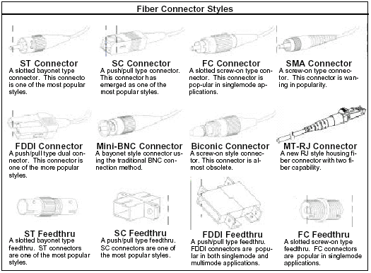
Few types of Fiber Optics Connectors currently being used in the market....
ST ST (an AT&T Trademark) is probably still the most popular connector for multimode networks (ca. 2005), like most buildings and campuses. It has a bayonet mount and a long cylindrical 2.5 mm ceramic (usually) or polymer ferrule to hold the fiber. Most ferrules are ceramic, but some are metal or plastic. And because they are spring-loaded, you have to make sure they are seated properly. If you have high loss, reconnect them to see if it makes a difference. The ST/SC/FC/FDDI/ESON connectors have the same ferrule size - 2.5 mm or about 0.1 inch - so they can be mixed and matched to each other using hybrid mating adapters. This makes it convenient to test, since you can have a set of multimode reference test cables with ST or SC connectors and adapt to all these connectors. |  |
| SC SC is a snap-in connector also with a 2.5 mm ferrule that is widely used for it's excellent performance. It was the connector standardized in TIA-568-A, but was not widely used at first because it was twice as expensive as a ST. Now it's only a bit more expensive and much more common It's a snap-in connector that latches with a simple push-pull motion. It is also available in a duplex configuration. |  |
| FC FC was one of the most popular singlemode connectors for many years. It also uses a 2.5 mm ferrule, but some of the early ones use ceramic inside stainless steel ferrules. It screws on firmly, but you must make sure you have the key aligned in the slot properly before tightening. It's been mostly replaced by SCs and LCs. |  |
| LC LC is a small form factor connector that uses a 1.25 mm ferrule, half the size of the SC. Otherwise, it's a standard ceramic ferrule connector, easily terminated with any adhesive. Good performance, highly favored for singlemode. The LC, MU and LX-5 use the same ferrule but cross-mating adapters are not easy to find. |  |
| FDDI - ESCON Besides the SC Duplex, you may occasionally see the FDDI and ESCON* duplex connectors which mate to their specific networks. They are generally used to connect to the equipment from a wall outlet, but the rest of the network will have ST or SC connectors. Since they both use 2.5 mm ferrules, they can be mated to SC or ST connectors with adapters. FDDI - above - has a fixed shroud over the ferrules ESCON - below - the shroud over the ferrules is spring-loaded and retracts
|
|
| MT-RJ MT-RJ is a duplex connector with both fibers in a single polymer ferrule. It uses pins for alignment and has male and female versions. Multimode only, field terminated only by prepolished/splice method. MT-RJ, Volition and Opti-Jack (below) are difficult connectors to test, as most test sets do not allow direct adaptation to the connector. If you have to use hybrid (ST or SC to MT-RJ) reference cables, you cannot do a Method B (one jumper reference) insertion loss test. Usually the solution is to do a three cable (Method C) reference. |  |
| Opti-Jack The Panduit Opti-Jack is a neat, rugged duplex connector cleverly designed aournd two ST-type ferrules in a package the size of a RJ-45. It has male and female (plug and jack) versions. |  |
| Volition 3M's Volition is a slick, inexpensive duplex connector that uses no ferrule at all. It aligns fibers in a V-groove like a splice. Plug and jack versions, but field terminate jacks only. |  |
| LX-5 LX-5 is like a LC but with a shutter over the end of the fiber. |  |
| MU MU looks a miniature SC with a 1.25 mm ferrule. It's more popular in Japan. |  |
| MT MT is a 12 fiber connector for ribbon cable. It's main use is for preterminated cable assemblies and cabling systems. Here is a 12 fiber MT broken out into 12 STs.
|  |
| Obsolete Connectors Deutsch 1000 Deutsch 1000 was probably the first commercially successful fiber optic connector. It was really a "pin vise" holding a stripped fiber. The nose piece is spring loaded and was pushed back when the connector was inserted into a mating adapter. The fiber stuck out into a drop of index matching fluid on a plastic lens. This solution was state of the art in the late 70s, yielding about 3 dB loss. Many users remember it as the connector on the front panel of the original Tektronix OTDR. |  |
| Obsolete Connectors SMA Amphenol developed the SMA from the "Subminiature A" hence SMA, microwave connector. The model 905 had a machined ferrule exactly 1/8 inch in diameter that mated in a machined adapter. When the adapters were not precise enough for better fibers, a necked-down ferrule that mated with a Delrin adapter for better insertion loss performance. These connectors are still in use on some military and industrial systems. |  |
| Obsolete Connectors BICONIC This is the Biconic, the yellow body indicating a SM version - MMs were usually black. Developed by a team led by Jack Cook at Bell Labs in Murray Hill, NJ, the Biconic was molded from a glass-filled plastic that was almost as hard as ceramic. It started with the fiber being molded into the ferrule. This lasted until the company could get a 125 micron/5mil pin insert into the plastic mold, at which point the fiber was glued into the ferule with epoxy. When singlemode versions first appeared, the ferrules were ground to center the fiber core in the ferrule to reduce loss. Since it was not keyed and could rotate in the mating adapters, it had an airgap between the ferrules when mated, meaning loss was never less than 0.3 dB due to fresnel reflection. Usually MM Biconics had losses of 0.5-1 dB and SM 0.7 dB or higher. Jacj Cook retired from Bell Labs and started Dorran Photonics which became 3M fiber optics. |  |
| Obsolete Connectors NEC D4 The NEC D4 was probably the first connector to use ceramic or hybrid ceramic/stainless steel ferrules. It uses a smaller ferrule than SCs or FCs. It was widely used in telco networks in the 80s to early 90s and some may still be in use. |  |
| Obsolete Connectors OPTIMATE The AMP optimate was popular in the early 80s. It used a conical plastic ferrule and screw-on nut. It was available for every fiber size including plastic fiber. Some may still be in use in utility and industrial systems. |  |


Typical Fiber Optic Connector Types | |
| Connector Style | Description |
| Biconic | Used in singlemode and multimode assemblies. An early connector design that is rarely used today. |
| | |
| D4 | Used in singlemode and multimode assemblies. A keyed, threaded connector that is rarely used today. |
| | |
| FC | Used in singlemode and multimode assemblies. Used in both computer networks and telecommunications applications. |
| | |
| FDDI | Used in multimode assemblies for computer networks; Always a duplex (2-fiber) assembly; Bodies are made of plastic with plastic or ceramic ferrules. |
| | |
| LC | Used in singlemode and multimode connector, adapters and associated components. The LC is a small form factor (SFF) connector that is ideal for high-density applications. |
| | |
| MIL-Spec | Generally used in multimode assemblies;. Made of aluminum or stainless steel; Available for multiple fiber cables. |
|
| |
| MPO/MPT | The MPO is a multi-fiber connector suitable for high-density backplane and printed circuit board (PCB) applications for data and telecom systems. MPO/MPT connectors offer up to 12-times the density of standard fiber optic connectors that results in significant space and cost savings. |
| | |
| MTRJ | Used in singlemode and multimode connector, adapters and associated components. The MTRJ is a small form factor (SFF) connector that uses a standard RJ-45 telephone plug interface providing a reliable and robust latching mechanism. The duplex ferrule concept is ideal for high-density applications. MTRJ adapters occupy the same space as a simplex SC adapter and meet the ANSI/TIA/EIA requirements. |
| | |
| MU | MU connectors are small form factor (SFF) connectors that provide superior singlemode or multimode optical performance. MU connectors are approximately half the size of a standard SC connector and feature a push-pull SC latching mechanism. In addition, MU connectors are feature low insertion losses, long-term reliability; and, repeatable performance characteristics. |
| | |
| SC | Used in singlemode and multimode assemblies. Used in both computer networks and telecommunications. Bodies are plastic with ceramic ferrules. Their small size allows them to be densely packed in patch panels and enclosure. |
| | |
| SMA | Used in multimode assemblies. Rarely used today. |
| | |
| SMC | The SMC connector is currently under consideration by the ANSI/TIA/EIA 604 Standards Committee as an industry standard connector. It is designed for use with 12-fiber optic ribbon cable and is based on the MT ferrule incorporating many features of the ESCON connector design. Three SMC connector configuration styles support jacketed and/or unjacketed cable for both internal and external applications. |
| | |
| ST | Used in singlemode and multimode assemblies. Used in both computer networks and telecommunications. Bodies and ferrules come in different materials, including plastic and metal. |
| | |


| Typical Fiber Optic Connector Ferrule Materials | |
| Connector Style | Description |
| Ceramic | Material used in both singlemode and multimode connectors. Most durable and produces the best performance. |
| Polymer | Composite plastic used in some multimode connectors and biconic singlemode connectors. Less expensive than ceramic. |
| Stainless Steel | Used only in multimode connectors |
Source
Subscribe to:
Posts (Atom)